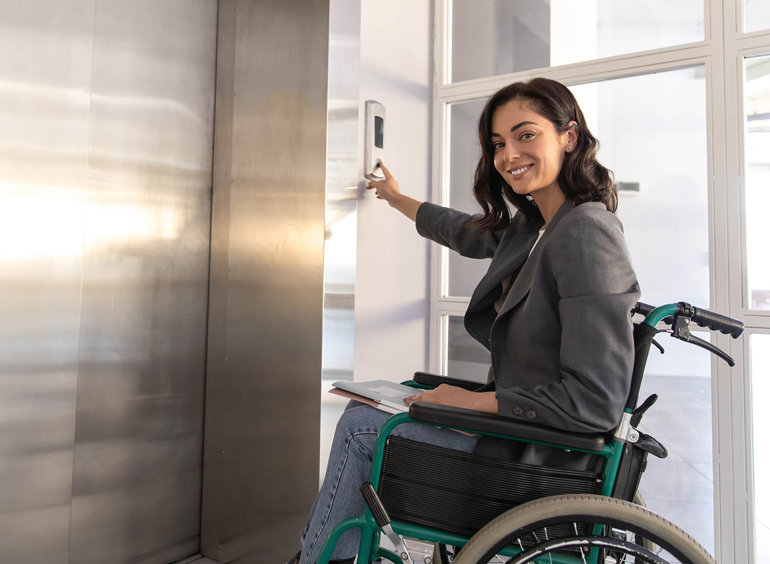
Driver-Assisted Evacuation Lift BS EN 81-76
Controlled by a designated person in the lift car
The driver-assisted evacuation lift is controlled by a designated individual from within the lift car. This system allows full control of the lift during an evacuation, with specific floors requiring evacuation clearly indicated.
A two-way audio intercom enables communication between the active Emergency Exit Landing (EEL) and the lift car.
Basic Functions
– Control of the lift via the car’s operation panel
– Registration of landing calls
– Display of calls within the lift car
Features of the Driver-Assisted Evacuation Lift
– An audio communication system connecting the lift car, EEL, and machinery spaces
– Voice announcements and visual indication devices in the lift car
– Compatibility with additional operation controls, including the option for automatic operation to be added
The iKONIC Driver-Assisted Evacuation Lift is available in two classifications:
Class A and Class B, allowing you to select based on your requirements.
As a simple guide, the information completed in your Evacuation Plan and capacity assessment will help you specify the correct operation and Class of Lift.
Class A Evacuation Lift is suitable if:
– The lift is not required to transport stretchers.
– Remote operation is not necessary.
– It is not required to be a firefighter lift since its travel distance is under 18 meters.
– Only one EEL is needed in the evacuation strategy.
– Specific landings do not need prioritisation in the evacuation plan.
– If there is no secondary power supply, a Class A lift can include an automatic rescue operation as part of the evacuation plan.
Class B Evacuation Lift is required if:
– The criteria for Class A are not met; the lift will be required to be a Class B Evacuation Lift.
Our evacuation lifts are designed, supplied, and installed according to:
BS EN 81-76 and comply with BS EN 81-20 and BS EN 81-70 standards.
The successful integration of an Evacuation Lift into a building relies on some non-related lift aspects; we find this information is critical for our clients to understand. Here is a simple PDF download that highlights the main ones:
| BASIC TECHNICAL INFORMATION | |
|---|---|
| STANDARDS | BS EN 81-76, BS EN 81-20, BS EN 81-70 |
| CLASS | A or B |
| OPERATION | Driver and/or Automatic |
| DUTY LOAD (Kg) | 630 - 2000 |
| RATED SPEED (m/s) | 1.0 – 1.6 |
| STARTS PER HOUR | 240 |
| MAX LIFT TRAVEL (M) | 17 or 50 |
| PIT (mm) | 1200* lower pits may be available |
| HEADROOM (mm) | 3200* lower headroom may be available |
| POWER SUPPLY (TNP) | 400 V 3 Phase 50 Hertz |
| DRIVE SYSTEM | Geared Traction |
| ENTRANCE OPTIONS | Single, (Through or Adjacent on request) |
| 2ND POWER SUPPLY | Available on request |
| MIN SIZE LIFT SHAFT (mm) | 1650mm x 1750mm |
| MIN SIZE LIFT SHAFT IF THROUGH CAR (mm) | 1650mm x 1920mm |
| MIN SIZE LIFT CAR (mm) | 1100mm x 1400mm |
| MIN SIZE LIFT ENTRANCE (mm) | 900 |


