
Automatic Evacuation Lift
Controlled by the building systems
Automatic Evacuation Lift Operation
The automatic operation of evacuation lifts is activated by an automatic evacuation signal from a fire alarm or building management system.
Basic Functions:
– Automatic control of the lift once triggered.
– Registration of landing calls.
– Serving landing calls:
– One by one to the Emergency Exit Landing (EEL).
– If the lift capacity allows, multiple calls may be served.
Features of the Automatic Evacuation Lift:
– Voice announcements and visual indication devices are provided in the lift car.
– Capability to set floor priorities.
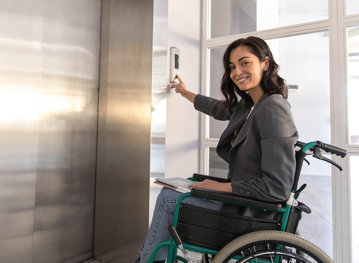
This evacuation system is particularly beneficial for the independent evacuation of individuals with disabilities, especially in situations where evacuation assistants may not be available or may take time to assist. Regular users of the building should be informed about the system and participate in regular evacuation drills. In the event of an evacuation, users of the evacuation lift should understand how to operate it and move to the designated safe area.
The lift can also function with other operational controls, including driver operation if desired.
iKONIC Lifts Automatic Evacuation Lift
Is available as either a Class A or Class B lift.
As a general guide, the information provided in your Evacuation Plan will help determine the appropriate class of lift.
Class A:
– The lift will not be required to transport stretchers.
– Remote operation is not required.
– The lift is not designated as a firefighter lift, as its travel distance is under 18 meters.
– Only one Emergency Exit Landing (EEL) is necessary for the evacuation strategy.
– No specific landing needs prioritization within the evacuation strategy.
– If there is no secondary power supply, a Class A lift may be included in the evacuation plan with an automatic rescue operation.
Class B:
– The criteria for Class A are not met.
– Remote evacuation is specified.
– Additional control operations are required if necessary.
Our evacuation lifts are designed, supplied, and installed according to BS EN 81-76 and comply with BS EN 81-20 and BS EN 81-70 standards.
The successful integration of an Evacuation Lift into a building relies on some non-related lift aspects; we find this information is critical for our clients to understand. Here is a simple PDF download that highlights the main ones:
| BASIC TECHNICAL INFORMATION | |
|---|---|
| STANDARDS | BS EN 81-76, BS EN 81-20, BS EN 81-70 |
| CLASS | A or B |
| OPERATION | Automatic and/or Driver |
| DUTY LOAD (Kg) | 630 - 2000 |
| RATED SPEED (m/s) | 1.0 – 1.6 |
| STARTS PER HOUR | 240 |
| MAX LIFT TRAVEL (M) | 17 or 50 |
| PIT (mm) | 1200* lower pits may be available |
| HEADROOM (mm) | 3200* lower headroom may be available |
| POWER SUPPLY (TNP) | 400 V 3 Phase 50 Hertz |
| DRIVE SYSTEM | Geared Traction |
| ENTRANCE OPTIONS | Single, (Through or Adjacent on request) |
| 2ND POWER SUPPLY | Available on request |
| MIN SIZE LIFT SHAFT (mm) | 1650mm x 1750mm |
| MIN SIZE LIFT SHAFT IF THROUGH CAR (mm) | 1650mm x 1920mm |
| MIN SIZE LIFT CAR (mm) | 1100mm x 1400mm |
| MIN SIZE LIFT ENTRANCE (mm) | 900 |